
APPROPRIATE APPLICATION OF DEHYDRATING BREATHERS TO REDUCE MOISTURE IN TRANSFORMERS AND LTCS
For transformers and LTCs to operate at their optimum level, transformer oil, a key part of the insulation system, must remain free of impurities that will lower its ability to function properly and efficiently. Three key impurities contribute significantly to the aging rate of a transformer: heat, oxygen and moisture. At least one, the moisture level, has a solution.
Every non-conservator equipped free breathing transformer/LTC has a headspace above the transformer oil level that is filled with a gaseous mixture. This headspace exists to allow for expansion and/or contraction of the oil volume due to load or environmental heating and cooling. During the heating cycle, the head space contracts, causing the transformer/LTC to exhale the differential volume of gas to the atmosphere. During the cooling cycle, the headspace expands, causing the transformer/LTC to inhale the differential volume from the atmosphere.
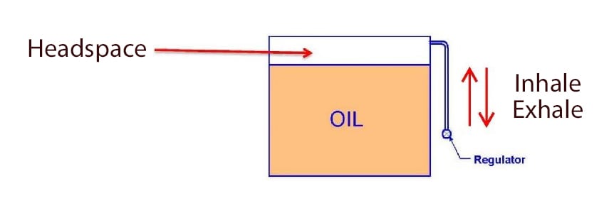
This air transfer without the use of a silica gel breather would contain the ambient level of moisture. This level could swing from 10% (Mojave Desert on a sunny day) to 99% during a foggy or rainy day anywhere in the USA. Why should we care? Because moisture in transformer oil affects the dielectric breakdown strength of oil, the temperature at which water vapor bubbles are formed, and the aging rate of the insulation materials (oil and paper), all of which could lead to a transformer failure.
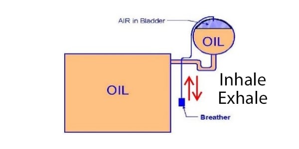
What about transformers with conservators, are they not immune to moisture since the oil is protected from contact with ambient air by the rubber bladder? Yes and No. The bladder, when intact, does protect oil from ambient air. Degradation/Service aging of the bladder material over time can impair the life of the bladder. In addition, since no easy way exists to inspect the bladder without actually opening the conservator tank, a rupture can occur and go unnoticed. In this case, the oil has the same exposure to ambient air and moisture as a free-breathing transformer without a conservator tank.
Therefore, what type of silica gel breather should be used? What are the pros and cons of each system?
A static, “dumb” silica gel breather has a relatively low upfront cost. However, it has a finite capacity to absorb moisture, and, therefore, its life is difficult to predict due to the multiple variables involved with the weather and equipment loading. This type of breather requires frequent visual monitoring since the unit lacks any type of self-monitoring. Once the capacity of the unit has been reached, silica gel must be replaced with new or recycled dry silica gel to avoid moist air from entering the equipment.
A properly designed auto regenerating dehydrating breather has more upfront expense but eliminates the need for frequent monitoring and replacement. These breathers are self-monitoring with the capability of remote reporting and will function for many years with only minor annual inspections.
In conclusion, protecting the oil in a transformer or LTC from moisture contamination is readily accomplished with minimal attention by using an automatic regenerating dehydrating silica gel breather, such as the Waukesha® Dual Column Breather.
AUTHOR:
Art Martin
Senior Product Engineer – Service & Components Division
PRODUCT INFORMATION ON THE NEW WAUKESHA® DUAL COLUMN BREATHER
The latest generation Waukesha® Auto Regenerating Dehydrating Breather System (Dual Column Breather is designed to remove moisture from the air entering transformer, LTC and conservator tanks as well as other sealed tanks. Regeneration is accomplished using Positive Temperature Coefficient (PTC) solid state heaters located in the central column and controlled by an adjustable timer and humidity sensor to provide automatic recharging of the silica gel desiccant, eliminating the need for manual intervention. The humidity sensor constantly monitors air from the in-service column and will force a column shift if the air stream humidity reaches the trigger point, regardless of the timer setting. The use of dual columns ensures that the unit does not have to wait for a “quiet time,” i.e. when the transformer in not inhaling, in order to regenerate. That enables the breather to have a fresh silica gel column continuously available for service. By adjusting the silica gel column regeneration cycle time, the system may be configured for various tank (air volumes) of 100 to 40,000 gallons or more.

Column “A” in Service

Column “B” in Service
During normal operation, air enters the breather through slots in the upper housing and passes through the desiccant to the center of the assembly. The center tube contains several holes along the entire length, forcing airflow to disperse through the maximum surface area of desiccant. Airflow then travels through the center tube, along a path—depending on the column in service—to the isolation solenoid and humidity sensor and eventually through the top port to the conditioned airspace.
During regeneration, a temperature regulating PTC heater element within the center tube of the column being regenerated, is energized to heat the desiccant to a specified temperature. Any moisture present in the desiccant is driven outward to the cooler borosilicate glass globe where it turns into condensate. The condensate runs to the bottom of the breather assembly where it is discharged through the water drain filter. In the arctic version, heat is automatically transferred to the drain to prevent freezing down to –50°C. During regeneration, the solenoid valve, located at the top of the breather assembly, isolates the column being regenerated while allowing the conditioned airspace to breathe through the column that is in-service. Once regeneration of the out-of-service column is complete (3 hours plus 30 minute cool down), the column is placed in stand-by mode. At the end of the in-service column cycle or if a column switch is triggered by the humidity sensor, the exhausted column is placed in regeneration mode and the stand-by column is placed in-service, ensuring a continuous supply of dry air to the conditioned airspace.
The Dual Column Breather system is shipped as a single integrated assembly and includes installed silica gel and accessories needed for mounting. The breather is constructed with a machined, anodized aluminum top, bottom and cast controls housing. Other components include heating elements, heat conductive fins, screen, condenser media and a filter vent system. Customer electrical and signal wiring is via conduit connections on the bottom of the control housing. The outer tube is optically clear borosilicate high strength glass. Sealed super bright LED lamps on the control cover provide clear visual indication of breather status, even in sunlight.
The Dual Column Breather systems feature an integrated PCB microcontroller that constantly monitors the condition of airflow through the breather. User adjustable, time-based controls regenerate the desiccant regardless of condition. Humidity sensing capability automatically overrides and regenerates the desiccant, if needed, between the set timer frequencies. Due to the dual column design, column regeneration is independent of the breathing status of the conditioned airspace.
The Dual Column Breather system is designed to be vertically mounted by means of four mounting tabs. Due to the dual column design, the mounting pattern is significantly different from our previous single column designs. An adapter plate is available from the previous mount pattern to that of the Dual Column Breather. An adapter kit is also available to accommodate the transition from previous cabled design to the conduit connections of the Dual Column Breather. The recommended connection to the conditioned space should be accomplished using standard flex hose and hose barbs (included), copper tubing, hard non-ferrous pipe or DIN 42562-5 flanged fitting.
In order to ensure that the Dual Column Breather system performs with exceptional reliability, it has been rigorously tested to IEC, EN, MIL and Prolec GE Waukesha internal standards. Five beta units are currently in service at diverse U.S. locations.
This new system features specifications designed to allow for ease of installation and operation:
- Wide range of input voltage tolerance, 100–240 VAC, 50–60 Hz
- Both time based and humidity based silica gel regeneration control
- Local system status SuperBrite LEDs for visibility is bright sun
- Remote monitoring of major system functions
Intelligent controls continuously monitor the status of the Dual Column Breather systems’ major components. The component’s status is reported via a combination of local LED signals and, for major faults, via an alarm relay, which may be monitored remotely. These include:
- Normal Operation (Green LED)
- Fast Mode operation (Flashing Green LED)
- Regeneration in Progress (Yellow LED)
- Humidity Sensor out of range (Blinking Yellow)
- Regeneration Heater Fault (Blinking Red LED & Remote alarm)
- Solenoid Fault (Red LED & Remote alarm)
- Power Failure (No LEDs Lit & Remote alarm)
The Dual Column Auto Regenerating Dehydrating Breather requires minimal annual maintenance:
- Check bottom drains for restrictions such as dust or other contaminants
- Visually check the silica gel for contamination, particularly transformer oil, which will show up as a dark or blackened color (transformer oil contaminated silica gel must be replaced)
- Clean the glass tube(s), if required
- Use glass cleaner or soap and water as solvents may degrade the rubber seals