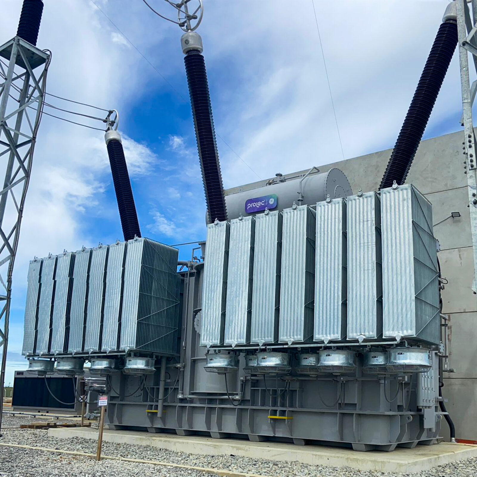
Generator Step-Up Transformers
Efficient Long-Distance Power Distribution
GSU transformers are used worldwide to raise voltages coming from power generation plants, including thermal, nuclear, and hydroelectric. Typical configurations require a Delta connected LV winding to induced currents in the Generator and Wye connected HV windings to connect to the transmission lines.
Prolec® GE and Waukesha® GSUs are engineered and manufactured to uphold the highest standards of reliability. By adhering to stringent quality control measures and utilizing top-grade materials and components, these transformers consistently exceed the expectations of our customers.

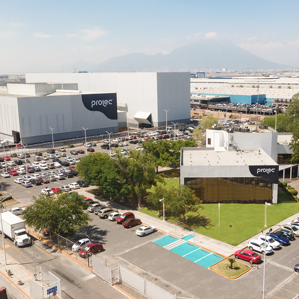
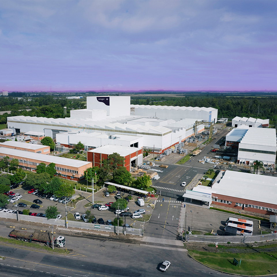
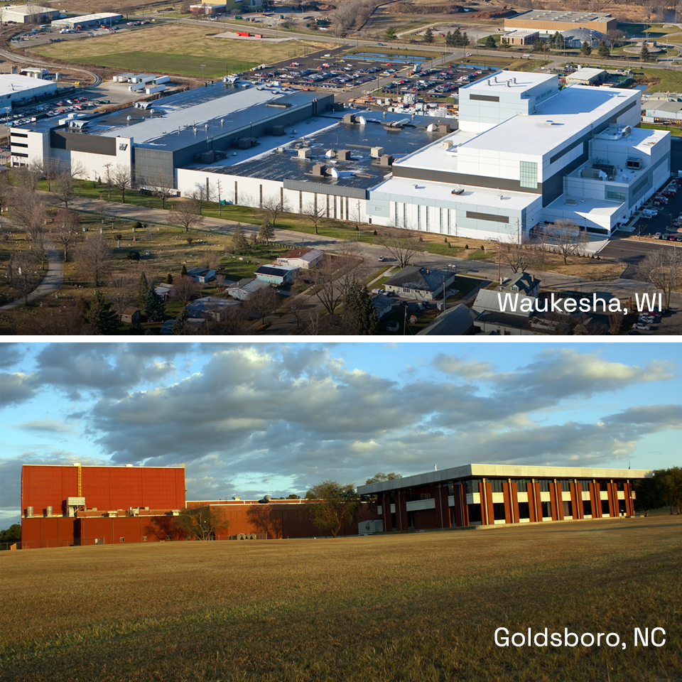
These transformers are manufactured in our Mexico, United States and Brazil facilities.
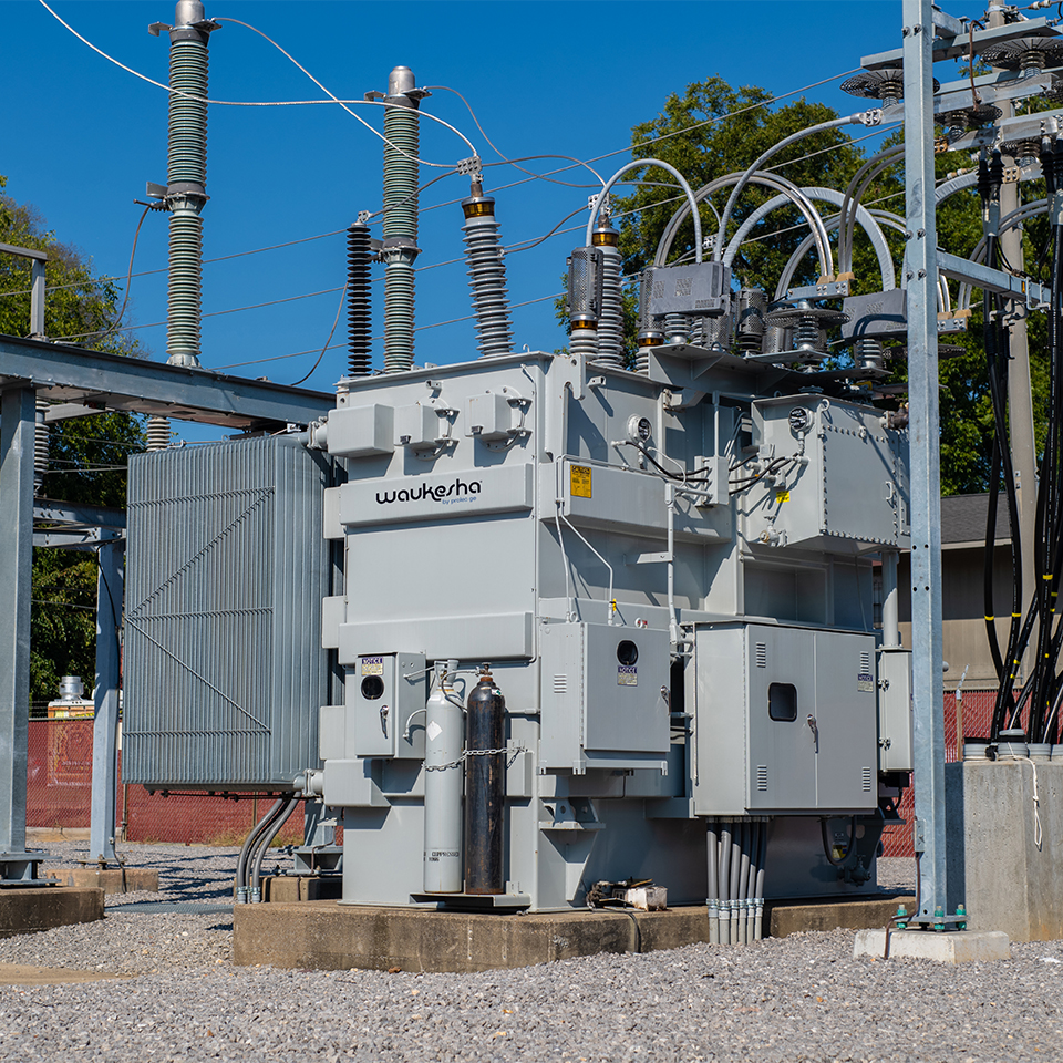
Standard GSU
GSU is a transformer directly connected to a generator. Generators are designed to produce constant voltage between 13 kV and 25 kV. These transformers then step up the voltage from the generator to match the transmission system.
Typical Ratings
- Low voltage: 13.2 kV through 25 kV – delta connection
- High voltage: 69 kV through 765 kV – wye connection
Plant Capabilities
- Up to 600 MVA single phase and 900 MVA three phase, up to 1000 MVA (Brazil facility)
- Up to 550kV (North American facilities), 800kV (Brazil facility) high voltage
Common Characteristics
- LTC will be on high voltage side (if required)
- Overload conditions are not required
- Sound requirements per NEMA TR1
- Large units with heat exchangers and pumps (OFAF, ODAF)
- Single phase banks (4 units total, 3+1 spare)
- LV bushings typically have isolated phase bus duct (high temp bushing)
Station Service
SSTs serve as backup power to a power plant and are fed from the grid.
Typical Ratings
- Under 50 MVA top rated
- High Voltage: 69 kV and above – delta or wye connection
- Low Voltage: 6 to 16 kV – typically wye connection
Plant Capabilities
- Up to 600 MVA single phase and 900 MVA three phase
- Up to 550kV high voltage
- Single or dual secondary windings (XV and YV, HV MVA equals XV MVA + YV MVA)
Common Characteristics
- Side mounted bushings common (LV typically)
- Air terminal chambers common
- LV neutral grounded through neutral grounding resistor (NGR)
Unit Auxiliary
UATs get power from a generator within a generation facility through the HV windings and distribute power to the plant through the XV windings. Since a generator will produce voltages unfavorable to facility operation, a transformer is needed to supply appropriate voltages.
Typical Ratings
- Under 50 MVA top rated
- Typically 8 kV, 18 kV and 21kV (typical generator voltages), stepping down from 6 to 4.16 kV (IEEE has suggested voltages) – delta – wye connection
Plant Capabilities
- Under 50 MVA top rated due to testing limits
- Up to 550kV high voltage
- Single or dual secondary windings (XV and YV, HV MVA equals XV MVA + YV MVA)
Common Characteristics
- Side mounted bushings common (LV typically)
- HV bushings typically have isolated phase bus duct (high temp bushing)
- Air terminal chambers common
- LV neutral grounded through neutral grounding resistor (NGR)
- Connected directly to generator